How to create an Azure storage lifecycle management policy
How to create an Azure storage lifecycle management policy
Whether you are using our Cloud Storage Management software to gain insights into your Azure storage environment, or are just trying to work out how to save costs within Azure, creating a lifecycle management policy is a great idea to help you save in your Azure storage costs.
Why is an Azure Lifecycle Management Policy important?
Azure Storage Lifecycle Management is a feature provided by Microsoft Azure that helps users manage the lifecycle of their data stored in Azure Blob storage. It allows users to transition their data to different storage tiers (Hot, Cool, Archive) based on their data access patterns and save costs in their Azure storage environment. The storage tiers have different costs per gigabyte of data, with the Hot tier being the most expensive and the Archive tier having the most cost savings. It is important because it enables users to save costs on their storage and manage their data effectively based on their business needs. Additionally, it helps ensure that the data is stored in the appropriate tier for its intended usage, improving performance and reducing costs.
Azure Storage Tiering Overview
Azure has three different tiers for your blob storage. These storage tiers are;
Hot – Used for frequently accessed data. Best suited for data that your user base accesses daily, think files and photos etc
Cool – Used for infrequently accessed data. Well suited for data that maybe accessed, but not that often.
Archive – Used for rarely accessed data, like backups or data that you need to keep for historical reasons.
Each of these Storage Tiers has a cost associated that Microsoft will charge you per gigabyte of data. The Hot Tier obviously being the most expensive, the Cool Tier is a little cheaper and the Archive Tier having considerable cost savings.
As an example at the time of writing this page, the cost per gigabyte in US dollars for each Tier is as below. (this may vary depending on your agreement with Microsoft)
Azure Blob Storage Costs
| PREMIUM | HOT | COOL | ARCHIVE | |
| First 50 terabyte (TB) / month | $0.15 per GB | $0.0184 per GB | $0.01 per GB | $0.00099 per GB |
| Next 450 TB/month | $0.15 per GB | $0.0177 per GB | $0.01 per GB | $0.00099 per GB |
| Over 500 TB/month | $0.15 per GB | $0.0170 per GB | $0.01 per GB | $0.00099 per GB |
As the table above shows, there are considerable savings when you move your blobs down to the lower tiers and creating an Azure Storage Lifecycle Management Policy.
Azure Blob Storage Tiering
Change your Storage Tier
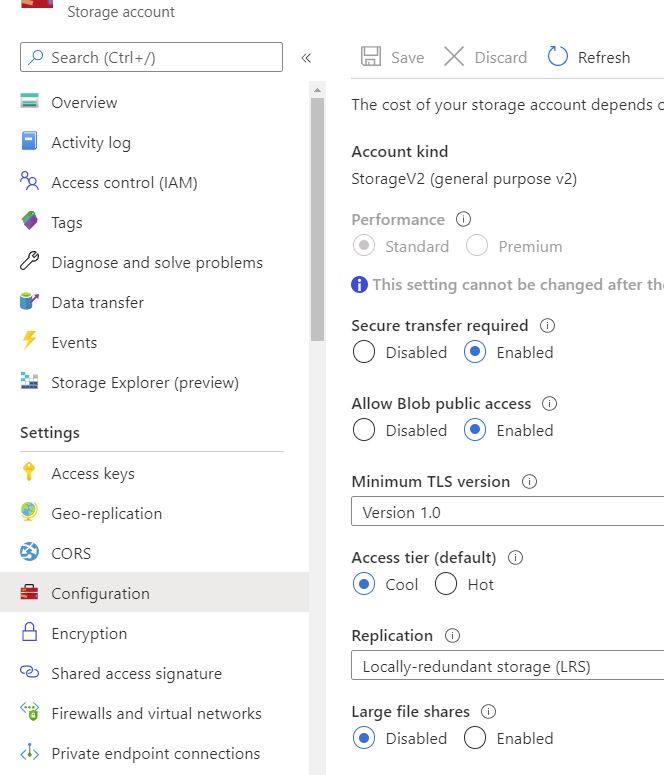
Microsoft Azure provides tiering for your blob data, that you can set as the default level. (either upon creation of the storage account or at a later date). To check the default storage tiering of your storage account go to the Azure Portal, choose configuration, and then the access tier that the blobs default to in that storage account is shown.
It must be noted that only the Hot and Cool tiers can be set as the default and not the Archive tier.
What are some of the benefits of creating an Azure Storage Lifecycle Management Policy?
OK, so now that you see there are some real benefits in changing the tiering of your blob storage, how do I create one you ask?
Well first off let’s look at what you will need to make sure is in place first.
Tiering of blob object storage is only available in Blob Storage and General Purpose v2 (or GPv2) accounts. If you have GPv1 storage you will need to convert that first to GPv2.
Premium storage does not provide any tiering, as this tier is for fast access using SSD based drives. (this maybe coming at a later date)
Changing tiers of storage may incur increased costs. Be very careful when applying the change to your data, as rehydrating blobs from the archive tier can be costly.
How to create your first Azure Storage Lifecycle Management Policy.
Open the Azure Portal
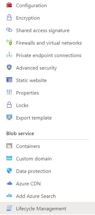
In your Azure portal, go to your storage account that you want the lifecycle policy to apply to and then choose Lifecycle Management.
Create a Azure Storage Lifecycle Policy Rule
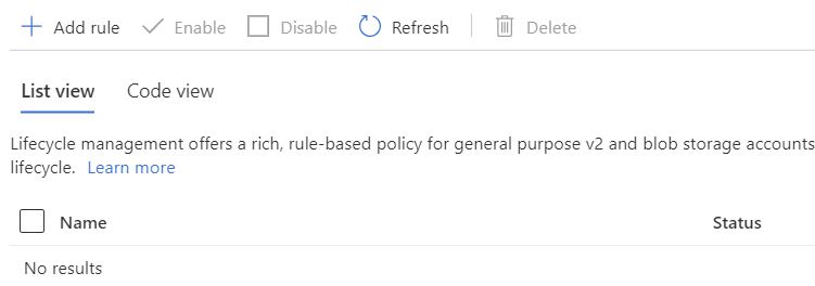
Once the right hand side of your browser has populated, choose Add Rule to start the wizard
Add Lifecycle Policy Rule
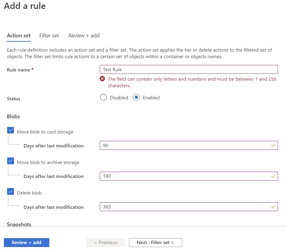
Now that the new rule has shown up we need to fill in a few details. You will need to give the rule a Name and then choose what you want to happen with your object data.
As an example I have shown in the below rule that the blobs will move to cool storage after not being accessed in 90 days, then to archive storage in 180 days, then finally being deleted in 365 days.
If you are happy with what you have set, just click Review + add and Azure will go on to apply those settings to your storage account, or if you want to be granular and exclude some containers / paths then click on Next: Filter Set.
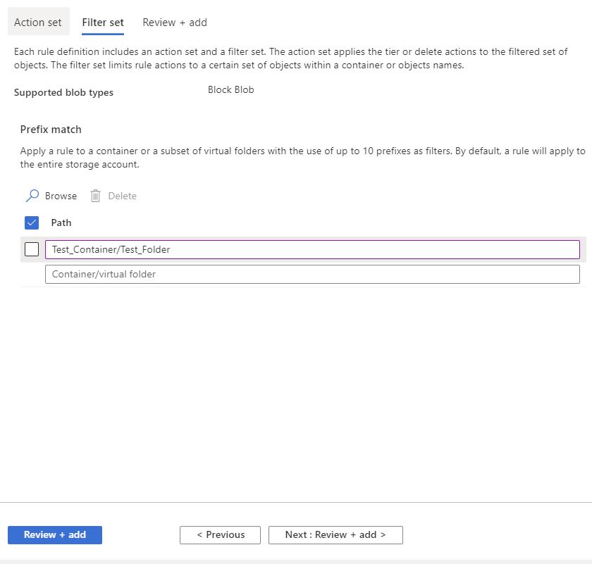
Azure Storage Lifecycle Policy Exclusions
On this page you can now exclude any containers or paths that you do not want this policy to apply to. Click Next: Review + add.
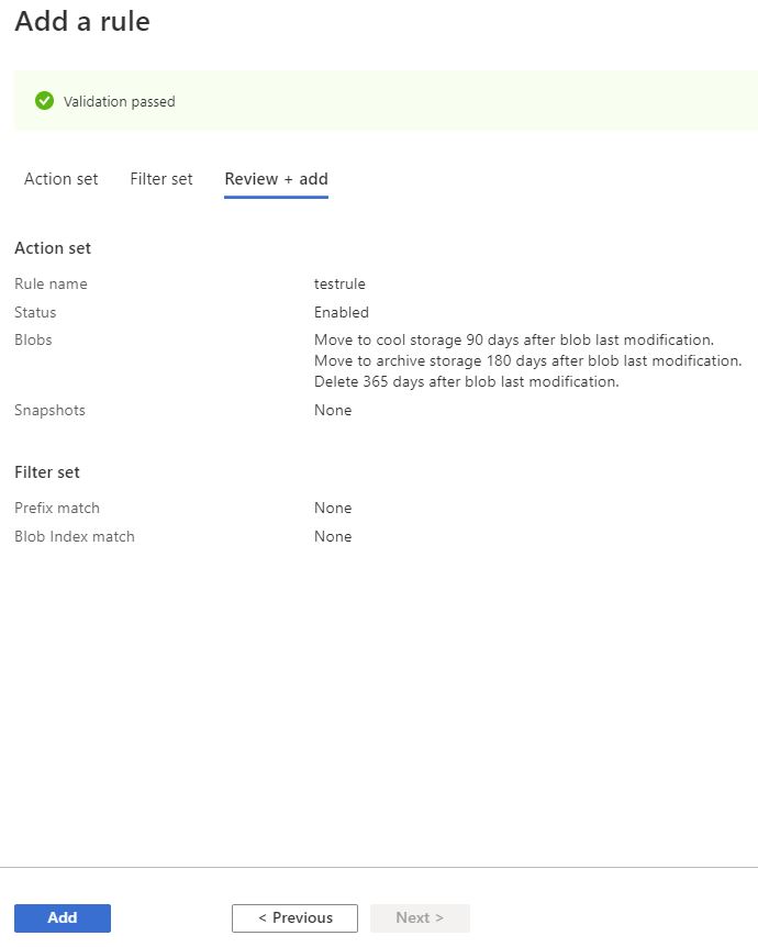
Azure Storage Lifecycle Validation
If all goes well you should be presented with a screen as below, saying that your Validation Passed.
Click on Add and Azure will now apply those settings to your storage account.
Azure will now go through all your Blobs and set them to the tiering and settings you have specified.
You have successfully created an Azure Storage Lifecycle Management Policy
Reduce your Azure Blob Storage Costs
Now you may ask, how do I know how much storage I’ve consumed or when were my blob files last accessed?
Easy. First run and install our Cloud Storage Manager software, then let it run a scan against your Azure Storage environments. Once the Scan has completed you can then run one of the many reports to understand and optimise your Azure Blob Storage.
Download a Free Trial and test it for yourself.
Free
![]()
Maximum Azure Storage limited to 30TB.
Typically for small or personal environments usually consisting of 3 or less Azure Subscriptions and consuming under 30TB of Azure Blob Storage.
Free Forever (until your Azure storage goes over 30TB).
Advanced
![]()
Maximum Azure Storage limited to 1PB
For medium sized environments typically consisting of less than 5 Azure Subscriptions.
Yearly license subscription of $500 USD per year which includes updates and support.
Enterprise
![]()
Unlimited Azure Storage.
For use in large environments typically consisting of more than 10 Subscriptions and consuming more than 1PB of Azure Blob Storage.
Yearly license subscription of $1000 USD per year which includes updates and support.
Cloud Storage Manager is licensed based on the size of your Azure Subscriptions, Azure Storage Accounts, Containers and finally each Blob.
Each version has the same great functions including scheduled scans of your Azure Blob Storage and reporting.
Send download link to:
FAQ for Azure Lifecycle Management
What is Azure Storage Lifecycle Management?
Azure Storage Lifecycle Management is a feature that allows users to automate the transition of their data to different storage tiers or classes based on the data’s age or access patterns.
How does Azure Storage Lifecycle Management help in reducing costs?
By automatically moving data to the appropriate storage tier based on its age or access patterns, Azure Storage Lifecycle Management helps to reduce storage costs by ensuring that you are only paying for the most expensive storage tier that you actually need.
Can I still access my data after it has been transitioned to a different storage tier?
Yes, you can still access your data even after it has been transitioned to a different storage tier. The only difference is the retrieval time, which may be slower for data stored in the Archive tier compared to the Hot and Cool tiers.
Can I revert a transition made by Azure Storage Lifecycle Management?
Yes, you can revert a transition made by Azure Storage Lifecycle Management, but you may incur additional charges for moving the data back to a more expensive storage tier.
Is Azure Storage Lifecycle Management available for all Azure storage services?
Currently, Azure Storage Lifecycle Management is available for Azure Blob storage.
What are the different storage tiers that can be managed by Azure Storage Lifecycle Management?
Azure Storage Lifecycle Management allows you to manage data across four storage tiers: hot, cool, archive, and deleted. The hot tier is for frequently accessed data, the cool tier is for infrequently accessed data, the archive tier is for rarely accessed data, and the deleted tier is for data that has been marked for deletion.
How does Azure Storage Lifecycle Management work with data protection?
Azure Storage Lifecycle Management integrates with Azure data protection features such as Azure Backup and Azure Site Recovery, to ensure that your data is protected even as it transitions between storage tiers.
Can I customize the transition policies for my data in Azure Storage Lifecycle Management?
Yes, you can create custom transition policies in Azure Storage Lifecycle Management that are specific to your data and your business requirements. You can specify the time-based or usage-based triggers for data transitions, and you can also set rules for data retention.
Can I track the data movement and monitor the performance of my storage infrastructure with Azure Storage Lifecycle Management?
Yes, you can use Azure Storage Lifecycle Management to monitor and track the data movement in your storage infrastructure, as well as to measure the performance of your storage tiers. You can also use Azure Monitor to set up alerts and notifications for specific events, such as data movement or storage tier changes.
Is Azure Storage Lifecycle Management supported for all types of data in Azure Storage?
Azure Storage Lifecycle Management is supported for all types of data in Azure Blob Storage, including block blobs, append blobs, and page blobs. It is not currently supported for other types of data in Azure Storage, such as files and queues.
Which storage account or storage accounts can you use lifecycle management?
The Storage Accounts that support Lifecycle Management Policies are Blob Storage Accounts that have block blobs and append blobs in general-purpose v2 and premium block blobs.