How to Update SCCM to Version 1902 – Quick Guide

How to Update SCCM to Version 1902 – Quick Guide

How to update to SCCM 1902

Microsoft System Center Configuration Manager (SCCM) is a powerful tool used by organizations to manage their IT infrastructure. SCCM allows IT administrators to manage operating systems, applications, and updates on a large number of devices. With the release of SCCM 1902, Microsoft has added new features and improvements to the software. If you are using an older version of SCCM, it is important to update to SCCM 1902 to take advantage of these new features.

In this article, we will provide you with a step-by-step guide on how to update to SCCM 1902.

SCCM 1902 New Features

  • Cloud Value
    • Cloud Management Gateway (CMG) can be associated with boundary groups – Cloud Management Gateway deployments can now be associated with boundary groups to allow clients to default or fallback to the CMG for client communication according to boundary group relationships.
    • Stop cloud service when it exceeds threshold – Configuration Manager can now stop a cloud management gateway (CMG) service when the total data transfer goes over your limit.
  • Application Management
    • Improvements to application approvals via email – When users request applications from Software Center, the email notification will now include their comments.
  • Configuration Manager console
    • Improvements to Configuration Manager console – Based on customer feedback aka the Cabana sessions at the Midwest Management Summit (MMS) Desert Edition 2018, this release includes several improvements to the Configuration Manager console.
    • View recently connected consoles – You can now view the most recent connections for the Configuration Manager console. The view includes active connections and those that recently connected.
    • View first monitor only during Configuration Manager remote control session – When connecting to a client with two or more monitors, a remote tools operator can now choose between seeing all monitors and the first monitor only.
    • Search device views using MAC address – you can now search for a MAC address in a device view of the Configuration Manager console.
  • Software Center
    • Replace toast notifications with dialog window – When deployments need a restart or software changes are required, you now have the option of using a more intrusive dialog window to replace toast notifications on the client
    • Configure default views in Software Center – You can now customize your end user’s default application layout and default application filter in Software Center.
  • OS Deployment
    • Improvements to task sequence media creation – When you create task sequence media, you can now customize the location that the site uses for temporary storage of data and add a label to the media.
    • Improvements to Run PowerShell Script task sequence step – The Run PowerShell Script task sequence step now allows you to specify a timeout value, alternate credentials, a working directory and success codes.
    • Import a single index of an Operating System Image – When importing a Windows image (WIM) file to Configuration Manager, you can now specify to automatically import a single index rather than all image indexes in the file.
    • Progress status during in-place upgrade task sequence – You now see a more detailed progress bar during a Windows 10 in-place upgrade task sequence.
  • Client Management
    • Client Health Dashboard – You can now view a dashboard with information about the client health of your environment. View your client health, scenario health, common errors along with breakdowns by operating system and client versions.
    • Specify a custom port for peer wakeup – You can now specify a custom port number for wake-up proxy.
  • Real-time management
    • Run CMPivot from the central administration site – Configuration Manager now supports running CMPivot from the central administration site in a hierarchy.
    • Edit or copy PowerShell scripts – You can now Edit or Copy an existing PowerShell script used with the Run Scripts feature.
  • Phased deployments
    • Dedicated monitoring for phased deployments – Phased deployments now have their own dedicated monitoring node, making it easier to identify phased deployments you have created and navigate to the phased deployment monitoring view.
    • Improvement to phased deployment success criteria – Specify additional criteria for the success of a phase in a phased deployment. Instead of only a percentage, these criteria can now also include the number of devices successfully deployed.
  • Office Management
    • Integration with analytics for Office 365 ProPlus readiness – Use Configuration Manager to identify devices with high confidence that are ready to upgrade to Office 365 ProPlus.
    • Additional languages for Office 365 updates – Configuration Manager now supports all supported languages for Office 365 client updates.
    • Office products on lifecycle dashboard – The product lifecycle dashboard now includes information for installed versions of Office 2003 through Office 2016.Redirect Windows known folders to OneDrive – Use Configuration Manager to move Windows known folders to OneDrive for Business. These folders include Desktop, Documents, and Pictures.
  • OS servicing
    • Optimized image servicing – When you apply software updates to an OS image, there’s a new option to optimize the output by removing any superseded updates.
    • Specify thread priority for feature updates in Windows 10 servicing – Adjust the priority with which clients install a feature update through Windows 10 servicing.
      Simplification
    • Management insight rules for collections – Management insights has new rules with recommendations on managing collections. Use these insights to simplify management and improve performance.
    • Distribution Point Maintenance Mode – You can now set a distribution point in maintenance mode. Enable maintenance mode when you’re installing software updates or making hardware changes to the server.
    • Configuration Manager Console Notifications – To keep you better informed so that you can take the appropriate action, the Configuration Manager console now notifies you when lifecycle and maintenance events occur in the environment.
    • In-console documentation dashboard – There is a new Documentation node in the new Community workspace. This node includes up-to-date information about Configuration Manager documentation and support articles.

SCCM 1902 FAQs

Question Answer

What is SCCM 1902?

SCCM 1902 is the latest version of System Center Configuration Manager, released by Microsoft in March 2019.

What are the new features in SCCM 1902?

SCCM 1902 comes with several new features, including the ability to deploy Win32 applications using Intune, improved device compliance, and enhanced cloud management.

What are the system requirements for SCCM 1902?

Operating System Requirements

  • Windows Server 2012 R2 or later
  • Windows 10 (Professional, Enterprise, or Education)
  • Windows 8.1 (Professional or Enterprise)
  • Windows 7 SP1 (Professional, Enterprise, or Ultimate)

Hardware Requirements

  • Processor: 64-bit processor with at least 4 cores
  • RAM: 8 GB of RAM or higher
  • Hard disk space: 500 GB or higher (depending on the size of the environment)
  • Network: 1 Gbps network adapter or faster

Software Requirements

  • Microsoft SQL Server 2012 SP4 or later
  • Microsoft .NET Framework 4.5.2 or later
  • Windows ADK 10 version 1809 or later (for deploying Windows 10)

Can I upgrade to SCCM 1902 from an older version?

Yes, you can upgrade to SCCM 1902 from an older version, but you need to follow the upgrade path and ensure that your infrastructure meets the prerequisites for the upgrade.

How do I upgrade to SCCM 1902?

You can upgrade to SCCM 1902 using the SCCM Console or command line, following a step-by-step process that includes downloading the update, running the prerequisite check, installing the update, and monitoring the progress.
Follow the guide below showing the exact steps to perform the upgrade

How long does it take to upgrade to SCCM 1902?

The time required to upgrade to SCCM 1902 depends on the size and complexity of your SCCM infrastructure, but it typically takes a few hours to complete the upgrade process.

What should I do after upgrading to SCCM 1902?

After upgrading to SCCM 1902, you should verify that your infrastructure is running the latest version, review and update your configuration settings, and test your SCCM infrastructure to ensure that all components are working correctly.

Where can I find more information about SCCM 1902?

You can find more information about SCCM 1902 in the Microsoft documentation, including release notes, installation guides, and troubleshooting guides.

SCCM 1902 Upgrade Process

Now, to upgrade to SCCM 1902 is quite an easy process, just follow these tasks below:
As with any upgrade or update, make sure you have an easy roll back position should anything cause an issue, either make sure you have a last known good backup or take a snapshot of your SCCM server prior to applying this update;

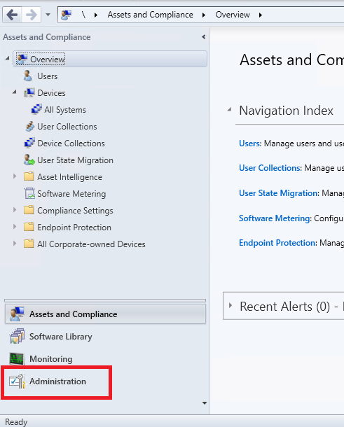
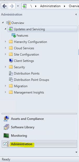
  1. Open your Configuration Manager Console and navigate to the Administration tab.
    SCCM 1902 Upgrade 1
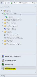
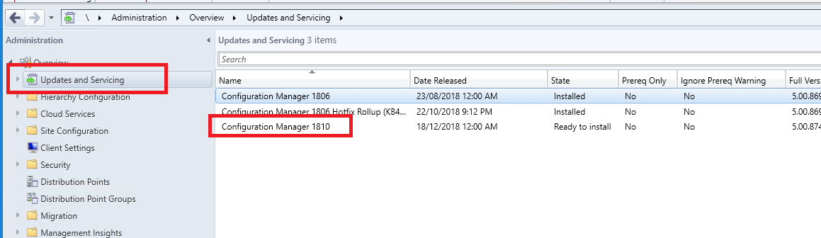
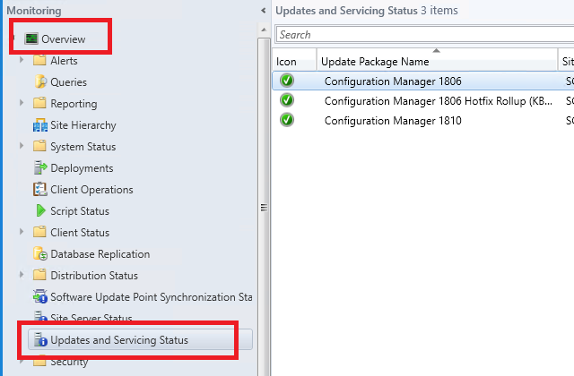
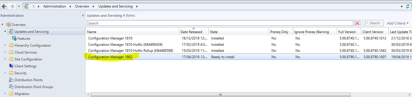
  2. Next we need to see if configuration manager has downloaded the SCCM 1902 update. Go click on Updates and Servicing and in the right side window, see if you have the update available.
    SCCM 1902 Upgrade 2
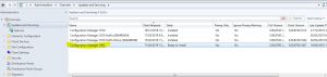
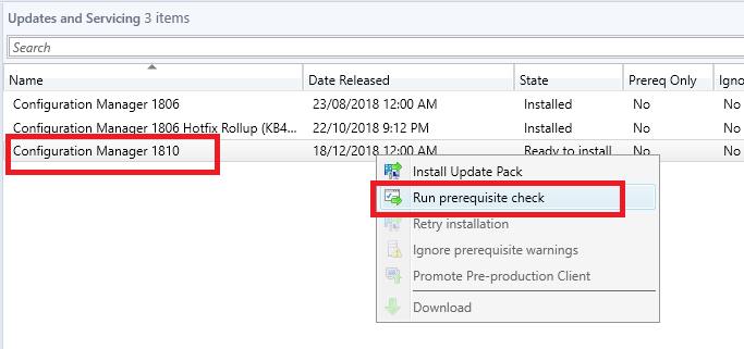
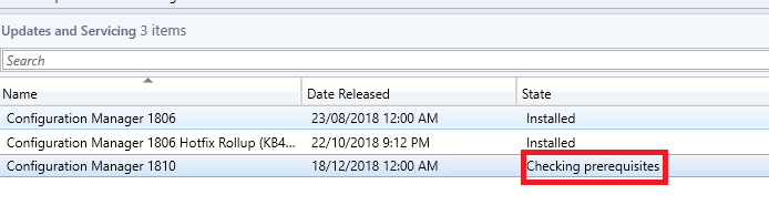
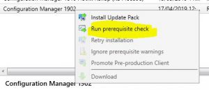
  3. Now we need to check the SCCM 1902 prerequisites are met before install this update. Right click the Configuration Manager 1902 update and choose Run Prerequisite Check.
    SCCM Upgrade Run Prerequisite Check
  4. The prerequisite check will run in the background. Keep refreshing your SCCM console to see the status of the check.
    SCCM Upgrade Checking Prerequisites
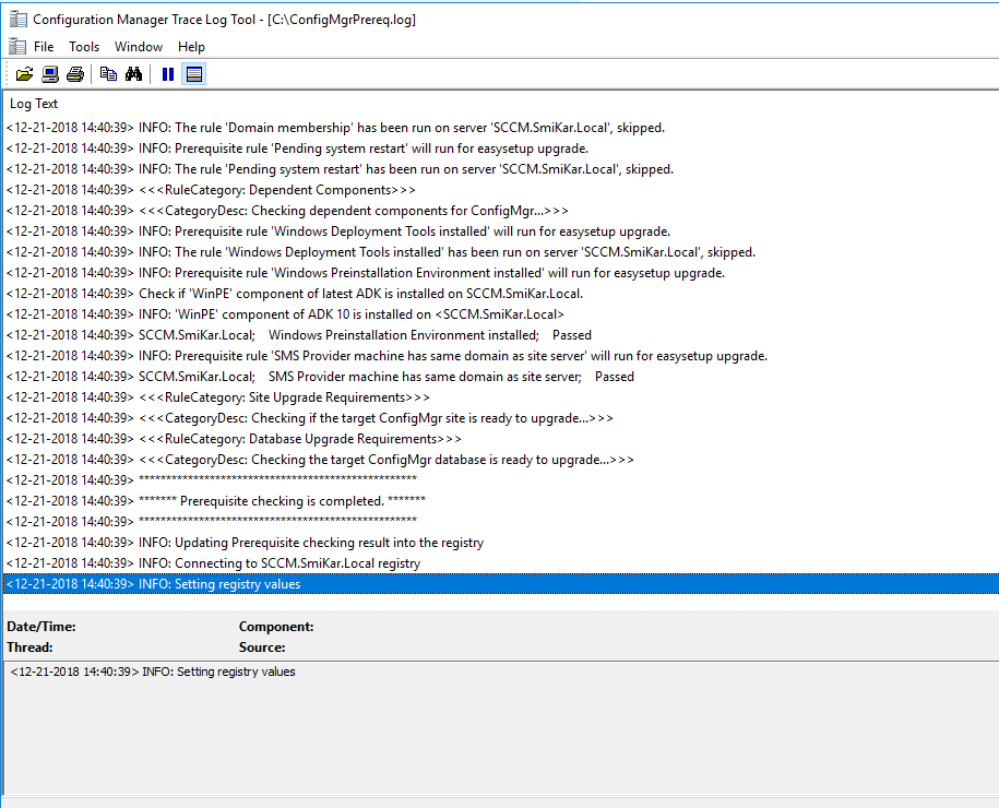
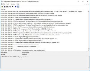
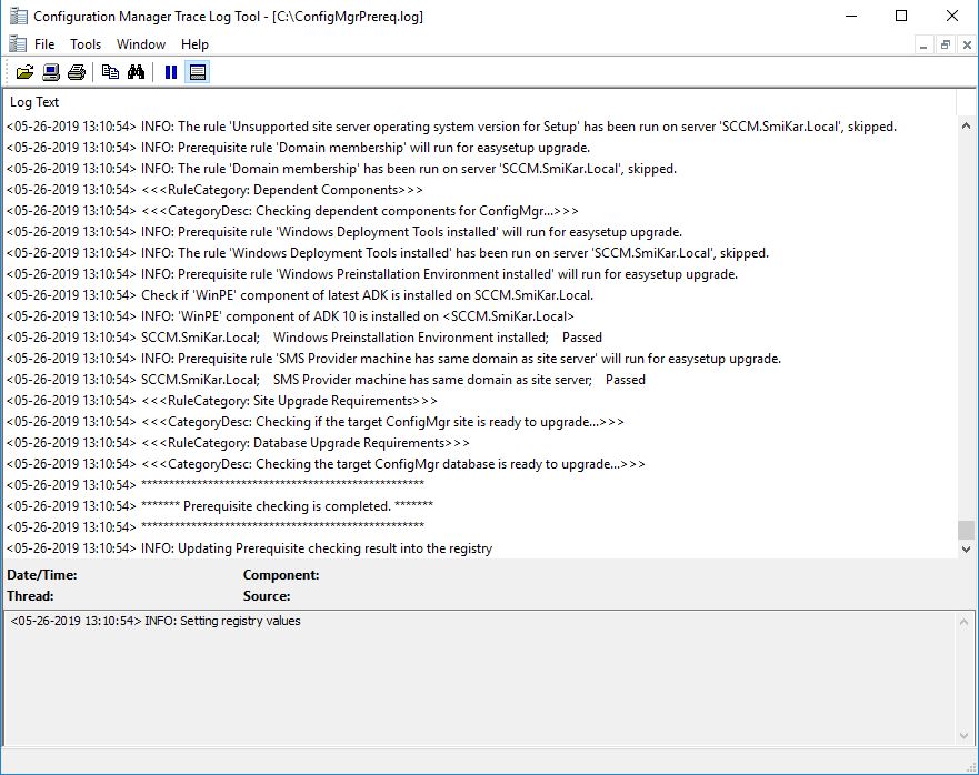
    You can also check the ConfigMgrPrereq.log located in your SCCM Server’s C Drive for further details of the sccm 1902 prerequisite check.
    SCCM 1902 Upgrade PreReqLog
    This may take some time (around ten minutes) so go grab a coffee or a cup of tea while you wait and hopefully when you come back and refresh your configuration manager console you see
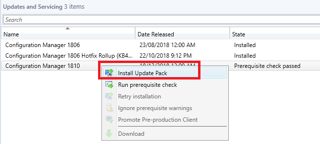
    Prerequisite Check Passed 
    SCCM 1902 Upgrade Prerequisite passed
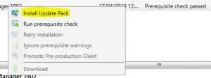
  5. Now on to the fun stuff, upgrade your configuration manager environment to SCCM 1902.
    Right click the Configuration Manager 1902 update and choose Install Update Pack.
    SCCM 1902 Upgrade Install Update Pack
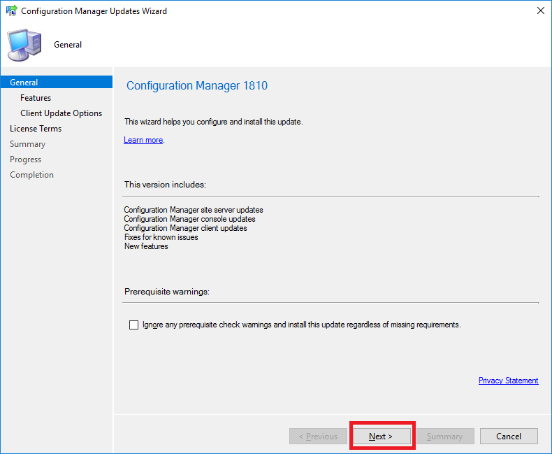
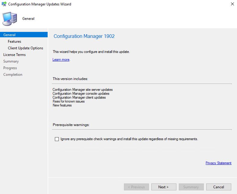
  6. The Configuration Manager Update Wizard now presents, ready for you to start the SCCM 1902 upgrade process. Click on Next to continue.
    SCCM 1902 Upgrade Wizard
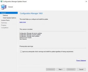
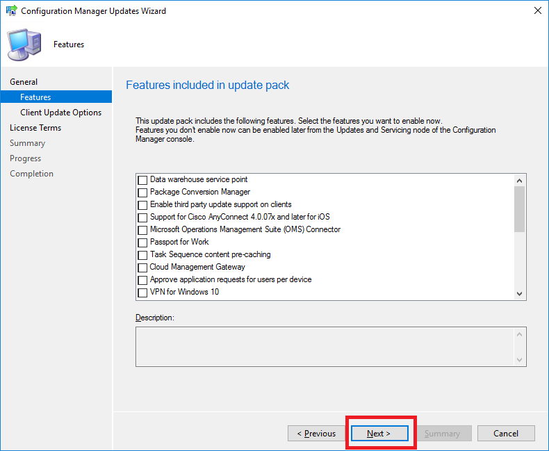
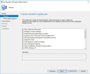
  7. We are now prompted with the features we wish to upgrade or install as part of this update. Carefully choose which features you need then click Next.
    SCCM 1902 Upgrade Features
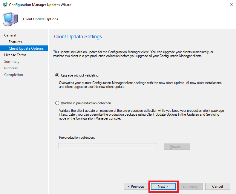
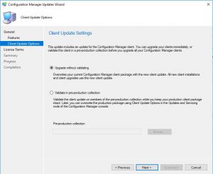
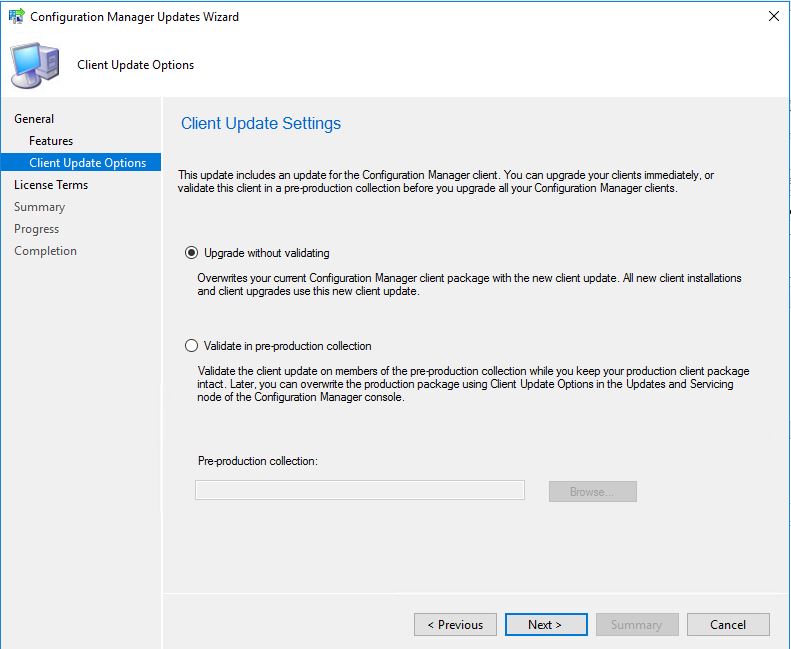
  8. If you have a preproduction collection to test the upgrade before deploying to your production collections, you can choose to do so on this screen. As this is one of our test labs, we wont go ahead with that and deploy this straight to production.
    SCCM 1902 Upgrade Collections
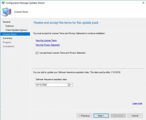
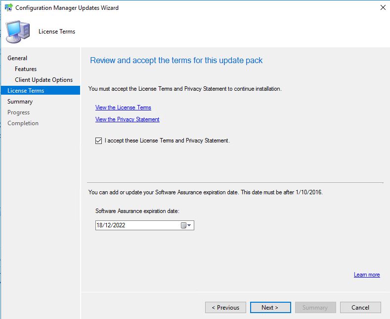
  9. You can review the license terms and conditions on this tab, make sure to check the checkbox to accept the terms of the license and then click Next.
    SCCM 1902 Upgrade License
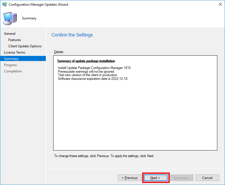
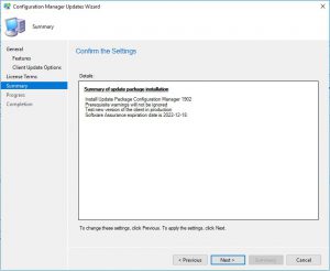
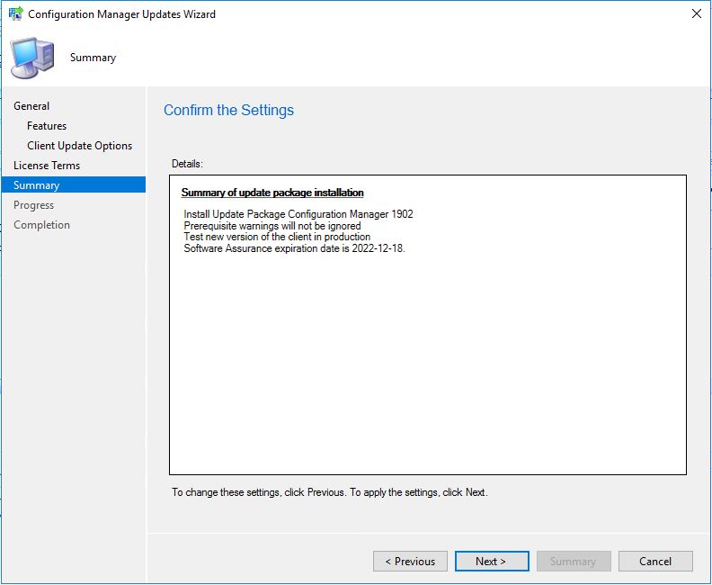
  10. Make sure on the Summary page that you have all the options you wish to upgrade or install displayed here, then click Next.
    When you click next this will now start the upgrade process for SCCM.
    SCCM 1902 Upgrade Summary
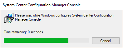
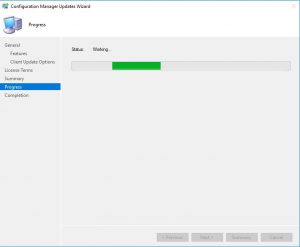
  11. Now the SCCM 1902 upgrade will start the update process.
    SCCM 1902 Upgrade Running
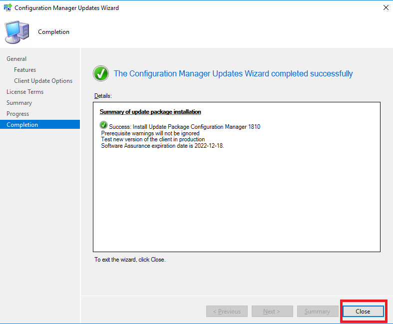
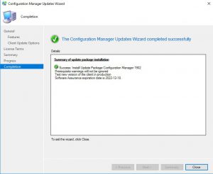
  12. The last screen is your completion screen, dont be fooled that it says completed, the update is still running and updating your SCCM infrastructure in the background.
    SCCM Upgrade 1902 Completed
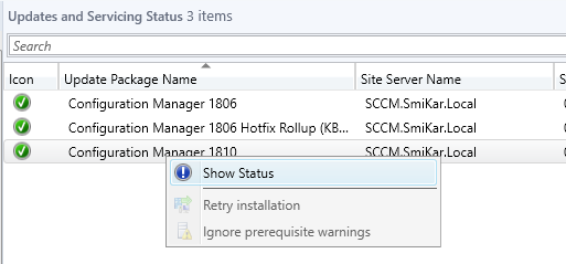
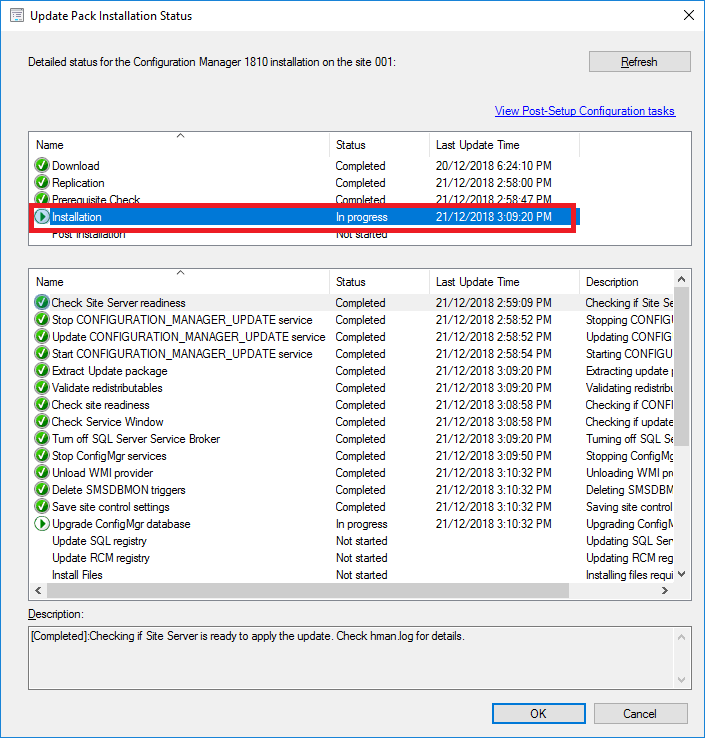
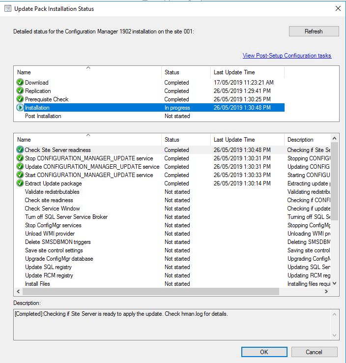
  13. To monitor the updates progress, go to the Monitoring tab, then Updates and Servicing Status. Choose the Configuration Manager 1902 update, then right click this then Show Status. From here, highlight Installation to watch the install status.
    SCCM Upgrade 1902 Install Status
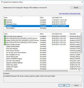
    In the above picture you can see that our SCCM environment is still installing the update.
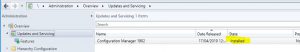
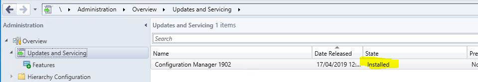
    The update process may take some time, expect around 30 minutes.
  14. Finally, after some time and the update process was successful, you should be able to see in the configuration manager console, that Configuration Manager 1902 has a state of Installed. SCCM 1902 Upgrade Successful
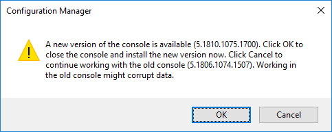
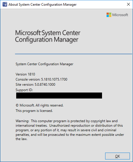
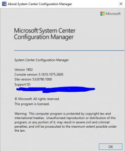
    You can also click About Configuration Manager under the drop down arrow in the top left corner of the configuration manager console to see what version you are running. If everything was successful, you should see the version of your SCCM now showing 1902.
    SCCM 1902 Upgrade Info

While you are here, dont forget to check out our software.

SnaPatch, which integrates with SCCM, VMware and HyperV to automate a snapshot then deploy patches to your virtual fleet.

SnapShot Master also integrates with VMware and HyperV and allows you to schedule snapshot creations then deletions.

Our Azure Management tools, that make your life easier to deploy, delete, shutdown and startup with orchestration of your Azure IAAS enviroment.

And finally, CARBON which replicates your Azure VMs back to your on-premise infrastructure with a simple few clicks.

Is Disaster Recovery Really Worth The Trouble (Part 4)

Is Disaster Recovery Really Worth The Trouble (Part 4)

Is Disaster Recovery Really Worth The Trouble

(Part 4 of 4 part series)

Guest Post by Tommy Tang – Cloud Evangelist

In this final chapter of the Disaster Recovery (part 1, part 2 and part 3) discussion I am going to explore some of the common practices, and myths, regarding DR in the Cloud. I’m sure you must have heard about the argument for deploying application to the Cloud because of the inherited built-in resilience and disaster recovery capability. Multi-AZ, 11 9’s durability, auto-scaling, Availability Sets and multi-region recovery (e.g. Azure Site Recovery) and many more, are widely adopted and embraced without hesitation. No doubt these resilient features are part of the charm of using Cloud services and each vendor will invest and promote their own unique strength and differentiation to win market share. It’ll only take 30 minutes to fail over to another AZ so she’ll be right, yes?

If you remember in Part 2 of the DR article I stated the number one resilience design principle is to “eliminate single point of failure”. Any Cloud vendor could also become the single point of failure. If you’ve deployed the well architected, highly modularised and API rich application in Amazon Web Services (AWS), do you still need to worry about DR? The short answer is YES. You ought to consider DR capability provided by AWS, or any other Cloud vendor for that matter, to determine whether it does meet your requirement. The solution is indeed fit for purpose. Do not assume anything just because it is in the Cloud.

AWS is not immune to unplanned outages because Could infrastructure is also built on physical devices like disks, compute and network switches. Some online stores like Big W and Afterpay had been impacted due to unexpected AWS outage on 14th Feb 2019 for about 2 hours. What is your Recovery Time Objective (RTO) requirement? Similarly Microsoft Azure is also not immune to outages either. On 1st February 2019 Microsoft had inadvertently deleted several Transparent Data Encryption (TDE) databases after encountering DNS issues. The TDE database were quickly restored from snapshot backup, but unfortunately customers would have lost 5 minutes worth of transactions. Image what would you do if your Recovery Point Objective (RPO) is meant to be Zero? No data loss?

At this very moment I hope I have stirred up plenty of emotions and a good dose of anxiety. Cloud infrastructure and Cloud service provider is not the imaginative Nirvana or Utopia that you have been searching for. It’s perhaps multi-generation better than what you have installed in your data centre today, but any Cloud deployment still warrants careful consideration, design and planning. I’m going to briefly discuss 3 areas in which you should start exploring in your own IT environment tomorrow.

Disaster Recovery Overview

1. Backup and Restore

As a common practice you’d take regular backup for your precious application and data so you’d be able to recover in the most unfortunate event. Same logic applies here when you have deployed applications in AWS or Azure Cloud. Ensure you are taking regular backup in the Cloud, which is likely to be auto-configured, as well as a secondary backup stored outside the Cloud service provider. It’s exactly the same concept and reason for taking offsite backup which is, proverbially speaking, you don’t put all your eggs in one basket. Unless you don’t have a data centre anymore, your own data centre would be the perfect offsite backup location. I understand getting backup off AWS S3 could pose a bit of challenge and I’d urge you to consider using AWS Storage Gateway for managing offsite backups. It should make backup management a lot easier.

Once you’ve secured the backup of application and data away from the Cloud vendor, you’re now empowered to restore (or relocate) the application to your own data centre or to different Cloud provider as desired. Bearing in mind that you’re likely to suffer some data loss using backup and restore technique. Depending on the backup cycle it’s typically a daily backup (i.e. 24 hours) or weekly backup (i.e. 7 days). You must diligently consider all recovery scenarios to determine if backup and restore is sufficed for the Recovery Point Objective (RPO) of the targeted application.

2. Data Replication

What if you can’t afford to lose data for your Tier-1 critical application? (i.e. RPO is Zero) Can you still deploy it to the Cloud? Again the short answer is YES but it probably requires some amendment to the existing architecture design, and notwithstanding the additional cost and effort involved. I believe I have already touched on the design patterns Active-Active and Active-Passive in Part 2 of the DR discussion. If Recovery Point Objective (RPO) is Zero then you must establish synchronous data replication across 2 sites, 2 regions or 2 separate Cloud vendors. Ok, even though it’s feasible to establish synchronous data replication over long distances, the Law of Physics still applies and that means your application performance is likely to suffer from elevated network latency. Is it still worth pursuing? It’s your call.

There are generally 2 ways to achieve data replication across multi-region or multi-cloud. The first method is to leverage storage replication technology. It’s the most common and proven data replication solution found in the modern data centre, however it’s extremely difficult to implement in the Cloud. The simple reason is you don’t own Cloud storage but vendors do. There will be limited API and software available for you to synchronise data say between AWS S3 and the on-premises EMC storage array. The only alternative solution I can think of, and you might have other brilliant idea, is to deploy your own Cloud edge storage (e.g. NetApp Cloud Volumes OnTap) and presented to the applications hosted in various Cloud vendors. Effectively you still own and manage the storage (and data) rather than utilising the unlimited storage generously provisioned by the vendor, and as such you are able to synchronise your storage to any secondary location of your choice. You have the power!

As opposed to using storage replication technology you can opt for host or software based replication. Generally you are probably more concerned of the data stored in database than say the configuration file saved on the Tomcat server. Following on this logic data replication at the database tier is our first and foremost consideration. If you are running Oracle database then you can choose to configure Data Guard with synchronous data replication between AWS EC2 and on-premises Linux database server. On the other hand if your preference is Microsoft SQL Server then you’d configure SQL Server Always On Cluster with synchronous replication for databases hosted in Azure Cloud and on-premises VMWare Windows server. You can even set up database replication between different Cloud vendors as long as the Cloud infrastructure supports it. The single most important prerequisite for implementing database replication, wether it is between Cloud vendors or Cloud to on-premises, is the underlying Operating System (OS). Ideally you’d have already standardised your on-premises operating environment to be Cloud ready. For example, retaining large scale AIX or Solaris servers in your data centre, rather than switching to Windows or Linux based Cloud compatible OS, does nothing to inspire a romantic Cloud story.

3. Orchestration Tool

The last area I’d like to explore is how to minimise RTO while recovering application to your on-premises data centre or to another Cloud vendor during major disaster event. If you are well versed in the DevOps world and being a good practitioner then you are already standing on good foundation. The most common problem found during recovery is the complexity and human intervention required to instantiate the targeted application software and hardware. Keeping with the true CI/CD spirit the proliferation use of orchestration tool to deploy immutable infrastructure and application is the very heart and soul of DevOps. By adopting the same principle you’d be able to recover the entire application stack via orchestration tool like Jenkins to another Cloud or on-premises Cloud like environment with minimal effort and time. No more human fat finger syndrome and slack think time during recovery. Consider using open source and Cloud vendor agnostic tool like Terraform (as opposed to AWS CloudFormation) can greatly enhance portability and reusability for recovery. Armed with the suitable containerisation technology (e.g. Kubernetes) that is harmonised in your IT landscape, you’d further enhance deployment flexibility and manageability. Running DR at an alternate site becomes a breeze.

In closing, I’d like to remind you that just because your application is deployed to the Cloud (i.e. someone else infrastructure) you are not exonerated from neglecting the basic Disaster Recovery design principles and making ill-informed decision. Certainly it’s my opinion that the buck will stop with you when the application is blown to smithereens in the Cloud. This is the last article of the Disaster Recovery series and hopefully I have imparted a little bit of the knowledge, practical examples and stories to you that you can tackle DR from a whole new light without fear and prejudice. I’m looking forward to sharing with you some more Cloud stories in a not too distant future. Stay tuned.

This article is a guest post by Tommy Tang (https://www.linkedin.com/in/tangtommy/). Tommy is a well rounded and knowledgeable Cloud Evangelist with over 25+ years IT experience covering many industries like Telco, Finance, Banking and Government agencies in Australia. He is currently focusing on the Cloud phenomena and ways to best advise customers on their often confused and thorny Cloud journey.

Is Disaster Recovery Really Worth The Trouble (Part 3)

Is Disaster Recovery Really Worth The Trouble (Part 3)

Is Disaster Recovery Really Worth The Trouble

(Part 3 of 4 part series)

Guest Post by Tommy Tang – Cloud Evangelist

In previous articles (part 1 and part 2) I’ve emphasised Disaster Recovery (DR) design principle is simply about eliminating single point of failure for data centre, and to provide adequate service and application resilience that’s fit for purpose. Over-engineered gold plated architecture solution does not always fit the bill and conversely low-tech simple and cost effective solution doesn’t necessary mean it’s sub-standard. There are 3 common DR patterns that you are likely to find in your organisation and they are known as “Active-Active”, “Active-Passive” and “Active-Cold”. As a DR solution architect you have been tasked to implement the most cost effective and satisfactory DR solution for your stakeholders. You might wonder where to begin, Pros and Cons of each DR pattern and what are the gotchas? Well, let me tell you there is no perfect solution or “one-size-fit-all” silver bullet. But don’t feel despair as I will be sharing with you some of the key design consideration and relevant technology that is instrumental to successful DR implementation.

Network and Distance Consideration 

Imagine your two data centres that are geographically dispersed, the underlying network infrastructure (e.g DWDM or MPLS) is the very bloodline that interconnects every service together such as HTTP server, database, storage, Active Directory, backup etc. So without doubt network performance and capability is rated high on my checklist. How do we measure and attain good network performance? First of all you’d need to understand the two key measurements; network latency and bandwidth and I will briefly explain them below.

Network latency is defined as the time it takes to transfer a data packet from destination A to B and expressed in Millisecond (ms). In some cases latency also includes the data packet roundtrip with acknowledgement (ACK). Network bandwidth is the maximum data transfer rate between destination A and B (aka network throughput), and the transfer rate is expressed in Megabits per second (Mbps). Both of these metrics are governed by the law of physics (i.e. speed of light) so the distance in which separated the two data centres plays a pivotal role in determining the network performance and ultimately the effectiveness of DR implementation.

Having data centres located in Sydney and Melbourne sounds like a good risk mitigation strategy until you are confronted with the “Zero RPO” dilemma. How could you keep data in-sync between 2 data centres stretched over 800Km, leveraging the existing SAN storage based replication technology, without causing noticeable degradation to storage performance? How about the inconsistent user experience being felt by users who are farther away from the data centre? Remember the law of physics? Unless you own a telephony company or unlimited funds, trying to implement synchronous data replication over long distance, regardless whether it is host or storage based replication technology, will surely cost a large sum of money and not to mention the adverse IO performance impact.

For those brave souls who are game enough to implement dual site Active-Active extended Oracle RAC cluster, the maximum recommended distance between 2 sites is 100Km. However after taking into consideration of super-low network latency requirement and relatively high cost, it’s more palatable to implement extended Oracle RAC cluster in data centres that are 10-15Km apart. You may find similar distance constraint exists for other high availability DR technology. Active-Active pattern is especially sensitive to network latency because of the constant chit-chatting between services at both sites. If the distance between 2 data centres is becoming the major impediment for implementing Active-Active DR or synchronous data replication, then you should diligently pursue alternative solutions. It’s quite possible that Active-Passive or non-zero RPO is acceptable architecture so don’t be afraid to explore all options with your stakeholders.

Mix and Match Pattern

I have come across application systems which have been architected with the flurry of mix and match DR design flair that got me slightly bemused. Let us examine a simple example. A “Category A” service (i.e. highly critical customer facing) is composed of Active-Active DR pattern for the Web Server (pretty standard), Active-Passive pattern for the Oracle database (also stock standard), and Active-Cold pattern for the Windows application server. So you may ask what is the problem if RTO is being met?

As you may recall each DR pattern comes with predefined RTO capability and prescribed technology that underpins it. By combining different DR design patterns into a single architecture will undoubtedly dilute the desired DR capability. In this example the Active-Cold pattern is the lowest common denominator as far as capability is concerned, so it will inadvertently dictate the overall DR capability. The issue being is why would you invest in a relatively high cost and complex Active-Active pattern when the end result is comparable to the lowly Active-Cold design? The return on investment has greatly diminished by including lower calibre pattern such as Active-Cold in the mix.

Another point you should consider is can the mix and match design really stand up in the real DR situation and meet the expected RTO. I have heard the argument that the chosen design works perfectly well in the isolated application DR test. What about in the real DR situation when you are facing competing human resources (e.g. Sysadm, DBA, Network dude) and system resources like IOPS, CPU, Memory, Network etc. It’s my belief that all DR design patterns should be regularly tested in simulated DR scenario with many applications, in the interest of determining the true DR capability and effectiveness. You may find the mix and match DR architecture does not work as well as expected.

Finally the technology that underpins each DR pattern could have changed and evolved over time. Software vendors often change functionality and capability with future releases so DR pattern must be engineered to be adaptive to change. As a result there’s inherited risk for mixing different DR patterns that will certainly increase the dependency and complexity for maintaining expected DR capability in the fast changing technology landscape.

Mix and match DR pattern may sound like a good practical solution and in many cases it is driven by cost optimisation. However after consideration of the associated risks and pitfalls I’d recommend choosing the pattern that is best matched for the corresponding service criticality. Although it’s not a hard and fast rule but I do find the service to DR pattern mapping guidelines below are simple to understand and follow. You may also wish to come up with different set of guidelines that are more attuned to your IT landscape and requirement.

  1. Category A (Highly Critical) – Active-Active (preferred) or Active-Passive
  2. Category B (Critical) – Active-Passive (preferred) or Active-Cold
  3. Category C (Important) – Active-Passive or Active-Cold
  4. Category D (Insignificant) – Active-Cold
 Disaster Recovery 2

Automation

Last but not least I’d like to bring automation into DR discussion. In the current Cloud euphoria era automation is the very DNA that defines its existence and success. Many orchestration and automation tools are readily available for building compute infrastructure, programming API and PaaS services configuration just to list a few. The same set of tools can also be applied to DR implementation with great benefits.

In my mind there is no doubt that Active-Active is the best architecture pattern, however it does come with a hefty implementation price tag and design constraints. For example some application does not support distributed processing model (i.e. XA transaction) so it can’t run in dual-site Active-Active environment. Even for the all mighty Active-Active pattern automation can further improve RTO when applied appropriately. For instance client and application workload distribution via Global DNS Service or Global Traffic Manager (GTM) needed for DR can be automated via pre-configured smart policy. Following the same idea database failover can also be automated based on well tested configurable rules. This is where automation can simplify and vastly improve the quality of DR execution.

Same design principle applies to Active-Passive and Active-Cold DR pattern as well. Automation is the secret source for quality DR implementation. Consider incorporating automation to all service components where possible. But here is the reality check. Implementing automation is not trivial and it is especially difficult for service component that is not well documented or designed, or lack of the suitable automation tools. Furthermore it is not advised to automate DR process if there is no suitable production like environment (e.g. cross-site infrastructure) to conduct quality assurance test. The implementation work itself can be extremely frustrating because you’d need to delicately negotiate and cooperate with different departments and third-party vendors. Having that said I believe the benefits are far outweighed the pain in most cases. I have known one case where automation has reduced DR failover time from 4 hours down to 30 minutes. No pain no gain right?

For those who are DevOps savvy techies there are many orchestration tools out in the marketplace that you can pick to develop the automation framework of your choice. Chef, Puppet, Jenkins for orchestration and Python, Powershell, and C Shell for scripting just to name a few. If you don’t want to build your owner automation framework then you might want to consider vendor software like Selenium, Ansible Tower or Blueprism.

In conclusion a successful DR implementation should be planned with detailed impact assessment of network latency between data centres, carefully consider the most appropriate DR patterns and relevant technology for the targeted service application, and leverage automation infused with artificial intelligence (i.e. policy or rule based) to replace manual tasks where feasible. In the next article I will be exploring the various DR scenarios presented for Cloud deployment.

This article is a guest post by Tommy Tang (https://www.linkedin.com/in/tangtommy/). Tommy is a well rounded and knowledgeable Cloud Evangelist with over 25+ years IT experience covering many industries like Telco, Finance, Banking and Government agencies in Australia. He is currently focusing on the Cloud phenomena and ways to best advise customers on their often confused and thorny Cloud journey.

Is Disaster Recovery Really Worth The Trouble (Part 2)

Is Disaster Recovery Really Worth The Trouble (Part 2)

Is Disaster Recovery Really Worth The Trouble

(Part 2 of 4 part series)

Guest Post by Tommy Tang – Cloud Evangelist

In the previous article I’ve mentioned Architecture is the foundation, the bedrock, for implementing Disaster Recovery (DR), and it must be part of the broader discussion on system resilience and availability otherwise funding will be hard to come by. You may ask what are the key design criteria for DR? I believe, first and foremost, the design must be ‘Fit for Purpose’. In other words you’d need to understand what the customer wants in terms of requirement, objective and expected outcome. The following technical jargons are commonly used to measure DR capability and I will provide a brief explanation for each metric.

Recovery Time Objective (RTO)

  • It is the targeted time duration of which a service or system needs to be restored during Disaster Recovery. Typically RTO is measured in hours or days and it’s no surprise to find human ‘think’ time often exacerbates the recovery time. RTO should be tightly aligned with the Business Continuity requirement (i.e. Maximum Acceptable Outage MAO) given system recovery is only one aspect of the business service restoration process.

Recovery Point Objective (RPO)

  • It is the maximum targeted time of which data or transaction might be lost without recovery. You can view RPO as the maximum data loss that you can afford. So ‘Zero RPO’ is interpreted as no data loss is permitted. Not even a second. The actual amount of data loss is very much dependent on the affected system. For example, an online stock trading system that suffers a 5-minute data loss could result hundreds of lost transaction worth millions of dollars. Conversely, an in-house Human Resource (HR) system is unlikely to suffer any data loss for the same 5-minute interval given changes to HR system are scarce.

Mean Time To Recovery (MTTR)

  • It is the average time taken for a device, component or service to recover from failure after being detected. Unlike RTO and RPO, MTTR includes the element of monitoring and detection, and it’s not limited to DR event but any failure scenario. When you’re designing the appropriate DR solution for your customer, MTTR must be vigorously scrutinised for each software & hardware component in order to meet the targeted RTO.

Let’s move over to the business side of the DR coin and see how these metrics are being applied. I think it is a safe bet to assume each business service would have already been assigned to the predetermined service criticality classification, and each classification must have included RTO and RPO requirement. For illustration purposes let say “Category A” service is a highly critical customer portal so it might have 2-hour RTO and Zero RPO requirement, and for “Category C” internal timesheet service it could have RTO set to 12-hour with 1-hour RPO.

In a real DR event (or DR exercise) the classification is used to determine the order in which a service is being restored. It is neither practical or sensible to have all services weighed equally, or have too many services that are rated critical given the limited resources and immense pressure being exerted during DR. The right balance must be sought and agreed upon by all business owners.

Disaster Recovery

Now you have the basic understanding of the DR requirement and keen to get started. Hold off launching the Microsoft Visio app and start drawing those beautiful boxes just yet. I’d like to share with you the one simple resilience design principle which I have been using, and that is to eliminate “Single Point of Failure”. By the virtue of having 2 working and functionally identical components in the system you’d improve resilience by 100%! The 2x system is now capable of handling single component failure without loss of service. The “Single Point of Failure” principle does apply to physical data centre and therefore it is very much relevant to DR design.

As an IT architect you have a number of tried and proven solutions (aka architecture patterns) available in the toolkit at your disposal. The DR patterns described below are commonly found in most organisations.

Active-Active

The definition of Active-Active DR pattern is to provision two or more active working software components that spread across 2 data centres. E.g. A N-tier system architecture may consist of 2x Web servers, 2x Application servers and 2x Database servers. Client connection and application workload is distributed between 2 sites, either equally weighed or otherwise, via Global DNS Service or Global Traffic Manager (GTM). The primary objective of the Active-Active DR design is to eliminate data centre as single point of failure. Under this design there is no need to initiate failover during Disaster Recovery because an identical system is already running at the alternate site and sharing the application workload. (E.g. Zero RTO)

The Active-Active pattern is best suited for critical system or service (i.e. Category A) because of the high cost and complexity associated with implementing distributed system. Not every application is capable of running in a distributed environment across 2 sites. The reason could be attributed to software limitation like Global Sequencing or Two-Phase Commit. It’s highly desirable to have formulated a prescriptive Active-Active design pattern to help mitigate the inherited cost and risks, and to align with the existing technology investment and future roadmap.

The biggest challenge is often encountered at the database tier. Are you able to run the database simultaneously across 2 sites? If so, is the data being replicated synchronously or asynchronously? Designing a fully distributed database solution with zero data loss (i.e. Zero RPO) is not trivial. Obviously you can choose to implement a partial Active-Active solution where every component except the database is active across 2 sites. Alternatively, you may want to relax the RPO requirement to allow non-zero value so asynchronous data replication can be applied. (E.g. 5-minute RPO)

From general observation I’ve found critical system database is typically configured with a warm standby DB with Zero RPO, where failover operation can be manually initiated or automated. The warm standby DB configuration is also known as Active-Passive DR pattern of which is going to be explored further in the next section.

Recently I’ve heard a story about Disaster Recovery. A service owner proclaimed the targeted system is fully Active-Active across 2 sites during the DR exercise and therefore no failover is ever required. 30 minutes later the same service owner, with much reluctance, scrambled to contact the DBA team requesting an urgent Oracle DB failover to the DR site. A word of advice: many supposed to be Active-Active implementations are only truely Active-Active up to the database tier so it does pay to understand your system design. A one page high-level system architecture diagram with network flow should be suffice to summarise the DR capability without confusion.

Active-Passive

The Active-Passive DR pattern stipulates that there is one or more redundant software components configured in warm standby mode at the alternate data centre. DR failover operation can be either manually initiated or automated for each component in the predetermined order for the respective application stack. Client connection and application workload will be redirected to the active live data centre via Global DNS Service or Global Traffic Manager (GTM). Remember the key differentiator from Active-Active DR pattern is only one active site can accept and process workload while the passive site is in dormant.

The primary objective of the Active-Passive design is, same as Active-Active, to eliminate data centre as single point of failure but albeit with higher RTO value. Time required to failover will vary and is dependent on the underlying design and technology deployed for the corresponding software component. Component failover can typically take 5 to 30 minutes (or even longer) to complete. Therefore the aggregated component failover time + human think time is roughly equivalent to the RTO value. (E.g. 4-hour RTO)

The Active-Passive design is suitable for most systems because it is relatively simple and cost effective, The two key technology enablers are storage replication and application native replication. Leveraging the storage replication for DR is probably the most popular option because it is application agnostic. The storage replication technology itself is simple, mature and proven and it’s generally regarded to be low risk. The data being replicated between sites can be synchronous (i.e. Zero RPO) or asynchronous (i.e. Non-zero RPO) and both options are just as good depending on the RPO requirement.

As for the application specific replication it will typically utilise TCP/IP network to keep data in-sync between 2 sites. It could also be synchronous or asynchronous depending on the technology and configuration. The underlying replication technology is vendor specific and proprietary so you’d need to rely on the vendor’s tools for monitoring, configuration and problem diagnosis. For example, you may want to implement SQL Server Always On Availability Group for the warm standby DB so you’d have to learn how to manage and monitor Windows Server Failover Cluster (WSFC). Application native replication is often found at the database tier like SQL Server Always On or Oracle Data Guard. Every vendor would have published the recommended DR configuration so it’d be foolhardy not to follow their recommendation.

Active-Cold

Last of all it is about the Active-Cold DR pattern. This pattern is similar to Active-Passive except the software component at the alternate site has not been instantiated. In some case it may require a brand new virtual server for configuring and starting the application component. Or it may need to manually mount the replicated filesystem and then start up the application. Or it may require certain backup restoration process to recover the software to the desired operating state.

The word ‘Cold’ implies much work is needed, and whatever it takes, to bring the service online. In many cases it’ll take hours or even days to complete the recovery task. Hence RTO for Active-Cold design is expected to be larger than Active-Passive. However just because it takes longer to recover doesn’t mean it is a bad solution. For example, it is perfectly acceptable to take one or two days to recover an internal timesheet system without causing much outrage. Put it simply it is “Horses for Courses”. Also you can still achieve Zero RPO (i.e. no data loss) with Active-Cold design by leveraging synchronous storage replication between sites. Not bad at all!

In this article I have covered the common DR related metrics like RTO, RPO and MTTR. I have also shared with you the ‘Single Point of Failure’ resilience design principle which has served me well over the years. I have summarised, perhaps a tad longer than summary, the three common DR design patterns interlaced with practical examples and the patterns are: Active-ActiveActive-Passive and Active-Cold. I realised I might have gone a bit longer than expected in this article so I’m saving some of the interesting thoughts and stories for the next article which is focusing on DR implementation.

This article is a guest post by Tommy Tang (https://www.linkedin.com/in/tangtommy/). Tommy is a well rounded and knowledgeable Cloud Evangelist with over 25+ years IT experience covering many industries like Telco, Finance, Banking and Government agencies in Australia. He is currently focusing on the Cloud phenomena and ways to best advise customers on their often confused and thorny Cloud journey.

Is Disaster Recovery Really Worth The Trouble (Part 1)

Is Disaster Recovery Really Worth The Trouble (Part 1)

Is Disaster Recovery Really Worth The Trouble

(Part 1 of a 4 part series)

Guest Post by Tommy Tang – Cloud Evangelist 

Disaster Recovery

Often when you talk to your IT colleagues or business owners about protecting their precious system with adequate Disaster Recovery capability (aka DR), you will get the typical response like ‘I have no money for Disaster Recovery’ or ‘We don’t need Disaster Recovery because our system is highly available’. Before you blow your fuse and try to serve them a comprehensive lecture on why Disaster Recovery is important, you should understand the rationale behind their thinking.

People would normally associate the word ‘disaster’ to insurance policy. So it is about natural disaster event such as flooding, thunderstorm, earthquake or man made disaster like fire, loss of power or terrorist attack. These special events are ‘meant’ to happen infrequently that the inertia of human behaviour will try to brush that off, and in particularly when you are asking for money to improve Disaster Recovery capability!

You may ask how do you overcome such deep rooted prejudice towards DR in your organisation? The first thing you must do is DO NOT talk about Disaster Recovery alone. DR should be one of the subjects covered by the wider discussion regarding system resilience and availability. Before your IT manager or business sponsor going to cough up some hard fought budget for your disposal you’ll need to articulate the benefit in clear, precise and easily understood layman’s terms. Do not overplay the technology benefit such as ‘it’s highly modularised and flexible to change’ or ‘it’s loosely coupled micro-service design that is good for business growth’, or ‘it’s well-aligned to the hybrid Cloud architecture roadmap for the enterprise’. Quite frankly they don’t give a toss about technology as they only care about operations impact or business return.

 For IT manager it’s your job to paint the rosy picture on how a well designed and implemented DR system can help meet the expected Recovery Time Objective (RTO), minimise human error brought on by the pressure cooker like DR exercise, and save the manager from humiliation amongst the peers and superiors in the WAR room during a real DR event. As for the business sponsor it’s only natural not to spend money unless there is material benefit or consequence. You’ll need to apply the shock tactics that will scare the ‘G’ out of them. For certain system it’s not difficult to get the message across. For example, the Internet Banking system that requires urgent funding to improve DR capability and resilience. The consequences of not having the banking system available to customers during business hours will have severe material and reputation impact. The bad publicity generated in today’s omnipresent digital media is both brutal and scathing and will leave no place to hide.

So now you have done the hard sell and secured funding to work on the DR project, how would you go about delivering maximum value with limited resource? This could be the very golden ticket for you to ascend to the senior or executive position. Here is my simple 3 phase approach outlined below and I’m sure there are many ways to achieve the similar outcome.

Architecture

  • This is the foundation of a resilient and highly available design that can be applied to different systems and not just a gold plated one-size-fit-all solution. The design must be prescriptive but yet pragmatic with well defined cost and benefits.

Implementation

  • It has to be agile with risk mitigation strategy incorporated in all delivery phases. I believe automation is the key enabler to quality assurance, operational efficiency and manageability.

On-Premises and Cloud

  • The proliferation and adoption of Cloud has certainly changed the DR game. Many different conversations taking place today is about “To Cloud” or “Not To Cloud”, and if it is Cloud then HOW? Disaster Recovery must be, along with system resilience, included into such critical decision, and it’s ought to be adaptive to whatever path the business has chosen.

Understanding what DR really means in the organisation is utterly important and it can often lead to the change of prejudicial thinking with well articulated benefits and consequences. In the coming weeks I’m going to share my insights for the aforementioned phase approach.

This article is a guest post by Tommy Tang (https://www.linkedin.com/in/tangtommy/). Tommy is a well rounded and knowledgeable Cloud Evangelist with over 25+ years IT experience covering many industries like Telco, Finance, Banking and Government agencies in Australia. He is currently focusing on the Cloud phenomena and ways to best advise customers on their often confused and thorny Cloud journey. 

How to upgrade to SCCM 1810

How to upgrade to SCCM 1810

Step by step how to upgrade SCCM to version 1810

What’s new in SCCM 1810?

Here is a quick run down of the exciting new features that Microsoft has added to SCCM for release 1810. You can see more information around this update on the Microsoft blog site.

Specify the drive for offline OS image servicing

Now you can specify the drive that Configuration Manager uses when adding software updates to OS images and OS upgrade packages.

Task sequence support for boundary groups

When a device runs a task sequence and needs to acquire content, it now uses boundary group behaviors similar to the Configuration Manager client.

Improvements to driver maintenance

Driver packages now have additional metadata fields for Manufacturer and Model which can be used to tag driver packages for general housekeeping.

Phased deployment of software updates

You can now create phased deployments for software updates. Phased deployments allow you to orchestrate a coordinated, sequenced rollout of software based on customizable criteria and groups.

Management insights dashboard

The Management Insights node now includes a graphical dashboard. This dashboard displays an overview of the rule states, which makes it easier for you to show your progress.

Management insights rule for peer cache source client version

The Management Insights node has a new rule to identify clients that serve as a peer cache source but haven’t upgraded from a pre-1806 client version.

Improvement to lifecycle dashboard

The product lifecycle dashboard now includes information for System Center 2012 Configuration Manager and later.

Windows Autopilot for existing devices task sequence template

This new native Configuration Manager task sequence allows you to reimage and re-provision an existing Windows 7 device into an AAD joined, co-managed Windows 10 using Windows Autopilot user-driven mode.

Improvements to co-management dashboard

The co-management dashboard is enhanced with more detailed information about enrollment status.

Required app compliance policy for co-managed devices

You can now define compliance policy rules in Configuration Manager for required applications. This app assessment is part of the overall compliance state sent to Microsoft Intune for co-managed devices.

SMS Provider API

The SMS Provider now provides read-only API interoperability access to WMI over HTTPS.

Site system on Windows cluster node

The Configuration Manager setup process no longer blocks installation of the site server role on a computer with the Windows role for Failover Clustering. With this change, you can create a highly available site with fewer servers by using SQL Always On and a site server in passive mode.

Configuration Manager administrator authentication

You can now specify the minimum authentication level for administrators to access Configuration Manager sites.

Improvements to CMPivot

CMPivot now allows you to save your favorite queries and create collections from the query summary tab. Over 100 new queryable entities added, including for extended hardware inventory properties. Additional improvements to performance.

New client notification action to wake up device

You can now wake up clients from the Configuration Manager console, even if the client isn’t on the same subnet as the site server.

New boundary group options

Boundary groups now include two new settings to give you more control over content distribution in your environment.

Improvements to collection evaluation

There are two changes to collection evaluation scheduling behavior that can improve site performance.

Approve application requests via email

you can now configure email notifications for application approval requests.

Repair applications

You can now specify a repair command line for Windows Installer and Script Installer deployment types.

Convert applications to MSIX

Now you can convert your existing Windows Installer (.msi) applications to the MSIX format.

Improvement to data warehouse

 You can now synchronize more tables from the site database to the data warehouse.

Support Center

Use Support Center for client troubleshooting, real-time log viewing, or capturing the state of a Configuration Manager client computer for later analysis. Find the Support Center installer on the site server in the cd.latestSMSSETUPToolsSupportCenter folder.

Support for Windows Server 2019

Configuration Manager now supports Windows Server 2019 and Windows Server, version 1809, as site systems.

SCCM 1810 prerequisites

As with any update, you should make sure that you have all the prerequisites to install this update to Configuration Manager, prior to starting the upgrade process.

These prerequisites to SCCM 1810 are;

  • Every site server within your existing Configuration Manager environment should be at the same version
  • To install the update, the minimum SCCM version you can currently be on is version 1710. 1802 and 1806 are also accepted
  • SQL 2017 CU2 Standard and Enterprise
  • SQL 2016 SP2 Standard and Enterprise
  • SQL 2016 SP1 Standard and Enterprise
  • SQL 2016 Standard and Enterprise
  • SQL 2014 SP3 Standard and Enterprise
  • SQL 2014 SP2 Standard and Enterprise
  • SQL 2014 SP1 Standard and Enterprise
  • SQL 2012 SP4 Standard and Enterprise
  • SQL 2012 SP4 Standard and Enterprise
  • SQL 2012 SP3 Standard and Enterprise
  • Windows Server x64
  • Windows Server 2012 R2 x64
  • Windows Server 2016
  • Windows Server 2019 version 1809

How to upgrade SCCM to release 1810.

Step 1 – Administration Tab

Open you System Centre Configuration Manager Console and navigate to Administration


Sccm 1810 Upgrade

Step 2 – Updates and Servicing

Now click on Updates and Servicing and hopefully you should see the Configuration Manager 1810 update as highlighted in the attached picture.


Sccm 1810 Upgrade Updates and Servicing

Step 3 – Check SCCM 1810 Prerequisites

Next, right click on the Configuration Manager 1810 update and choose Run Prerequisite Check


Step 4 – Checking Prerequisites

Now the SCCM 1810 prerequisites will run and check that the Configuration Manager 1810 update is compatible with your current system. This will take some time, so perhaps go make a coffee while you wait.


Step 5 – ConfigMgrPrereq.log

You can check the status of the prerequisite check by looking at the ConfigMgrPrereq.log located in the C: drive of your configuration management server.

As you can see in my logs, the prequisite check has passed.


SCCM 1810 ConfigMgrPrereq_log

Step 6 – Install Update Pack

Now the fun stuff begins. We are ready to start the upgrade process for SCCM.

Right click the Configuration Manger 1810 update and choose Install Update Pack


Sccm 1810 Upgrade Install Update Pack

Step 7 – Start the installation process for SCCM 1810

On the Configuration Manager Updates Wizard, you can choose to Ignore any prerequisite check warnings and install this update regardless of missing requirements if you so wish.

As with any production environment, it’s always best case to never ignore any warnings, but we have had none in the previous check, so do not need to click this checkbox.

When you are ready to start the update process, click next.


Step 8 – Features included in update pack

The next page on the wizard are various features you can install as part of this update.

Check if any of the features you will need and when ready click on next.


Step 9 – Review and accept the terms

You can review the license terms that Microsoft has for this update. Accept these by checking the checkbox and click Next


Step 10 – Summary

Review this page to confirm that all the settings and features you have chosen previously are correct, and again when ready click Next.


Step 11 – Installation Completed

Finally, the last screen of the Configuration Manager 1810 upgrade wizard is the completed screen. Review the summary and then click on Close.

SCCM will upgrade in the background. This can take sometime dependent on your infrastructure setup.


Step 12 – Check Installation Status

To check the status of your SCCM upgrade, you need to go to Overview, then Updates and Servicing Status. 


Step 13 – Show Upgrade Status

Select the Configuration Manager 1810, then right click and choose Show Status.


Sccm 1810 Upgrade Show Status

Step 14 – Update Pack Installation Status

Highlight Installation and you will see the status of all the components that are upgrading.

Keep on clicking Refresh until you see all the tasks with a green tick. Be mindful, this does take sometime.

Click on Close when they are all green.


Sccm 1810 Upgrade Show Status 2

Step 15 – Update the Configuration Manager Console

Once all the ticks have gone green, click refresh within the SCCM console and you should be prompted with the Console Update.

Click on OK to proceed.


Sccm 1810 Upgrade Console Update

Step 16 – Update the Configuration Manager Console

The SCCM console update will download the required files and update your configuration manager console to the latest version


Sccm 1810 Upgrade Console Update 3

Step 17 – SCCM 1810 Upgrade Finished

Finally, SCCM has updated your Config Manager environment to release 1810


Sccm 1810 Upgrade Finish

How to Snapshot your VMs before patching with SCCM and SnaPatch

Now that you have upgraded SCCM to the current branch 1810, here is a quick run down on how to use SnaPatch with SCCM to quickly and easily snapshot your VMs prior patching.